Products
News
Whatsapp
Skype
Wechat
Chargers, server racks, and industrial controllers need steady voltage, even when incoming electricity fluctuates. A Switching Power Supply converts electrical energy by switching power transistors rapidly, then shaping and regulating the output. Unlike a traditional linear supply, it can often deliver comparable power with less heat and a smaller transformer. The details matter. A circuit typically rectifies incoming AC, switches it at high frequency, transfers energy through magnetic components, and filters the output. Feedback helps maintain the requested voltage when the load changes.
The scale of electricity use makes conversion efficiency more than a bench-top concern. The International Energy Agency’s Electricity 2024 report recorded a 2.2% rise in global electricity demand in 2023 and projected average annual growth of 3.4% for 2024–2026. Meanwhile, the U.S. Department of Energy’s 2024 report, based on Lawrence Berkeley National Laboratory analysis, estimated that data centers used about 4.4% of U.S. electricity in 2023. It projected a possible 6.7%–12% share by 2028. These figures do not measure power-supply losses alone, but they show why efficient conversion deserves attention.
This guide explains the main stages, components, and operating principles behind switching supplies. It also looks at efficiency, regulation, heat, and common design trade-offs. A high efficiency rating is useful, but it does not tell the whole story. Load conditions, cooling, and component quality matter too. Real circuits are messier than diagrams.
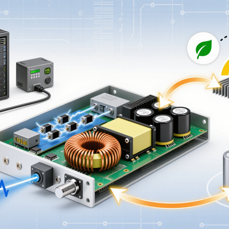
A switching power supply converts electrical energy from one voltage or current level to another. It rapidly turns a transistor on and off, then uses an inductor or transformer, capacitors, and control circuitry to shape the output. A feedback circuit checks the output and adjusts switching as the load or input changes. In an electronic system, this helps provide a stable supply to components that need specific operating voltages.
For example, a device may receive power from a 12-volt adapter but need a lower voltage for its processor. The supply switches energy in controlled pulses, stores some in its magnetic components, and smooths the resulting output with capacitors. Efficient conversion can reduce wasted energy and heat compared with many linear designs. Heat still matters. Component choice, airflow, and load affect real-world performance.
Switching supplies can also introduce electrical noise, so filtering and careful circuit layout matter, especially near sensitive audio or measurement circuits. Some designs provide electrical isolation; others do not, so that feature should never be assumed from the term alone. A supply’s label gives useful limits, but actual output quality can vary with operating conditions. Even a clean specification leaves questions. The system designer should check voltage range, current demand, ripple, temperature, and protection behavior against the application.
A switching power supply rapidly switches its input to regulate energy delivered to the load. This idealized waveform shows a 12 V to 5 V buck converter operating at 100 kHz (10 μs per cycle), with an approximately 41.7% duty cycle. Inductor current rises while the switch is on and falls while it is off.
A switching power supply converts incoming electrical power through three linked stages: rectification, high-frequency switching, and filtering. In an AC-powered design, a bridge rectifier uses four diodes to turn alternating current into pulsating direct current. A large capacitor then smooths the voltage into a relatively steady DC bus. It is not perfectly flat. Some ripple remains, and the capacitor can retain a dangerous charge after power is removed.
The switching stage rapidly turns a transistor on and off, often tens or hundreds of thousands of times per second. This creates controlled pulses rather than continuous current. A controller adjusts the pulse width in response to output conditions. In isolated designs, a transformer transfers energy between input and output while providing electrical separation. Other topologies use inductors without a transformer. Small details matter.
At the output, diodes or synchronous transistors rectify the pulses, while capacitors and inductors reduce ripple and electrical noise. Feedback measures the output and helps the controller compensate when a device draws more current. A multimeter may show the correct average voltage, yet a scope can reveal brief spikes or ripple. That distinction is easy to overlook. The stages are a useful mental model, though real circuits vary, and component tolerances, heat, and load changes can alter performance.
Buck, boost, and flyback converters solve different voltage-conversion problems by switching a transistor on and off rapidly. A buck converter steps voltage down. Its inductor and capacitor smooth the pulsing energy into a steadier output. Ideally, a 24-volt input at a 50 percent duty cycle produces about 12 volts, though real component losses change the result. It is common in devices that need lower internal voltages. Small details matter: poor layout can add electrical noise or unwanted heat.
A boost converter raises voltage. When its switch turns on, the inductor stores energy; when it turns off, that energy combines with the input to create a higher output. It cannot, in a basic arrangement, regulate below the input voltage. The flyback converter uses a coupled inductor, often called a transformer, to store energy during one part of the switching cycle and deliver it to the secondary during another. It can provide electrical isolation and multiple outputs, which makes it useful in compact adapters. But isolation is not automatic; the design and construction must support it. These models are useful, not perfect. Real waveforms ripple, and a tidy diagram never shows every stray effect. That deserves a closer look.
| Comparison Dimension | Buck Converter | Boost Converter | Flyback Converter |
|---|---|---|---|
| Basic function | Steps a DC input voltage down to a lower DC output voltage. | Steps a DC input voltage up to a higher DC output voltage. | Transfers energy through a coupled inductor to provide a DC output; it can step voltage up or down. |
| Ideal voltage relationship | Vout = D × Vin in continuous-conduction mode. | Vout = Vin / (1 − D) in continuous-conduction mode. | Vout / Vin ≈ (Ns / Np) × D / (1 − D) for an ideal converter in continuous-conduction mode. |
| Key energy-storage element | An inductor stores and releases energy as the switch turns on and off. | An inductor stores energy while the switch is on and releases it to the output while the switch is off. | A gapped coupled inductor stores energy in its magnetizing inductance during the primary switch’s on-time. |
| Typical power-stage components | Controlled switch, inductor, diode or synchronous switch, and output capacitor. | Controlled switch, inductor, diode or synchronous switch, and output capacitor. | Primary-side controlled switch, coupled inductor, secondary rectifier, and output capacitor. |
| How switching transfers energy | When the switch is on, the input supplies the inductor and load. When it is off, the inductor current continues through the freewheeling path. | When the switch is on, the inductor stores energy. When it is off, the inductor’s voltage adds to the input voltage and current flows to the output. | When the primary switch is on, energy is stored in the magnetic field and the secondary rectifier is generally off. When the switch turns off, the field collapses and energy is delivered to the secondary. |
| Galvanic isolation | Not provided by the basic topology. | Not provided by the basic topology. | Can provide galvanic isolation between input and output through separate transformer windings. |
| Input and output characteristics | Input current is pulsed in a basic implementation; the inductor helps provide relatively continuous output current. | Input current is relatively continuous through the inductor; output current is pulsed through the rectifier in a basic implementation. | Input and output currents are typically pulsed, so filtering is used to meet ripple requirements. |
| Notable design considerations | Requires the input voltage to exceed the regulated output voltage, allowing for conversion losses and control headroom. | A conventional diode-based boost stage has a direct input-to-output path and generally cannot regulate its output below the input voltage. | Requires careful transformer design, insulation, leakage-inductance control, and management of switch voltage spikes. |
| Common applications | Point-of-load regulators, processor supplies, and DC bus voltage reduction. | LED drivers, battery-powered equipment needing a higher rail, and DC bus voltage elevation. | Isolated auxiliary supplies, adapters, standby power supplies, and low-to-moderate-power isolated converters. |
A switching power supply regulates its output by rapidly turning semiconductor switches on and off. An inductor and capacitor smooth the resulting pulses into steadier direct current. A feedback circuit monitors the output and adjusts switching as the load changes. Switching rates commonly fall between 20 kHz and 1 MHz, though the actual rate depends on the design and operating conditions. That is fast. At 20 kHz, energy pulses arrive 20,000 times per second; at 1 MHz, they arrive one million times. This rapid cycling can allow smaller magnetic components than traditional line-frequency designs.
The switching rate affects component size, heat, noise, and filtering needs. Higher rates may reduce the size of inductors and transformers, but switching losses can increase, and unwanted electrical noise becomes harder to manage. Designers balance these trade-offs rather than simply choosing the highest possible frequency. A technician checking a supply might use an oscilloscope to observe switching waveforms, while measuring output ripple under a real load. One detail can be misleading: a stated frequency alone does not reveal performance. Some circuits vary their rate with load, and measurements can differ between operating modes. In practice, the whole circuit matters.
A switching power supply rapidly switches transistors, then filters the pulses into stable DC. Well-designed units commonly reach 80–95% efficiency, but performance shifts with load, temperature, and output voltage. At 90% efficiency, delivering 100 watts means roughly 11 watts become heat. Heat tells the story. That warmth affects nearby components, making airflow and thermal design important alongside the efficiency rating.
The U.S. Department of Energy’s external power supply test procedure, 10 CFR Part 430, Appendix Z, measures average active-mode efficiency and no-load power under defined conditions. These measurements help compare supplies, but they do not promise identical results in every installation. A unit running at light load may behave differently from one near its rated output. One detail is easy to miss: efficiency figures depend on the test method and operating point.
Safety comes separately. IEC 62368-1:2023 sets a hazard-based approach for information and communications technology equipment, covering electrical, fire, and energy-related hazards. Assessments consider safeguards such as insulation, spacing, enclosure strength, and temperature rise. Compliance does not make a supply safe in every enclosure; wiring and ventilation still matter. Check the model’s test documentation, input range, and safety markings before integration. Paperwork feels less tangible than a temperature reading, but both deserve attention.